Most off grid solar power system failures don’t happen during installation. They happen months earlier, on a spreadsheet — or worse, without one. Undersized battery banks, mismatched inverters, and arrays built for summer that collapse in December all trace back to the same root cause: sizing done wrong at the start. Getting that math right isn’t optional. It’s the entire job.
Why Off Grid Solar Power System Sizing Determines Project Success
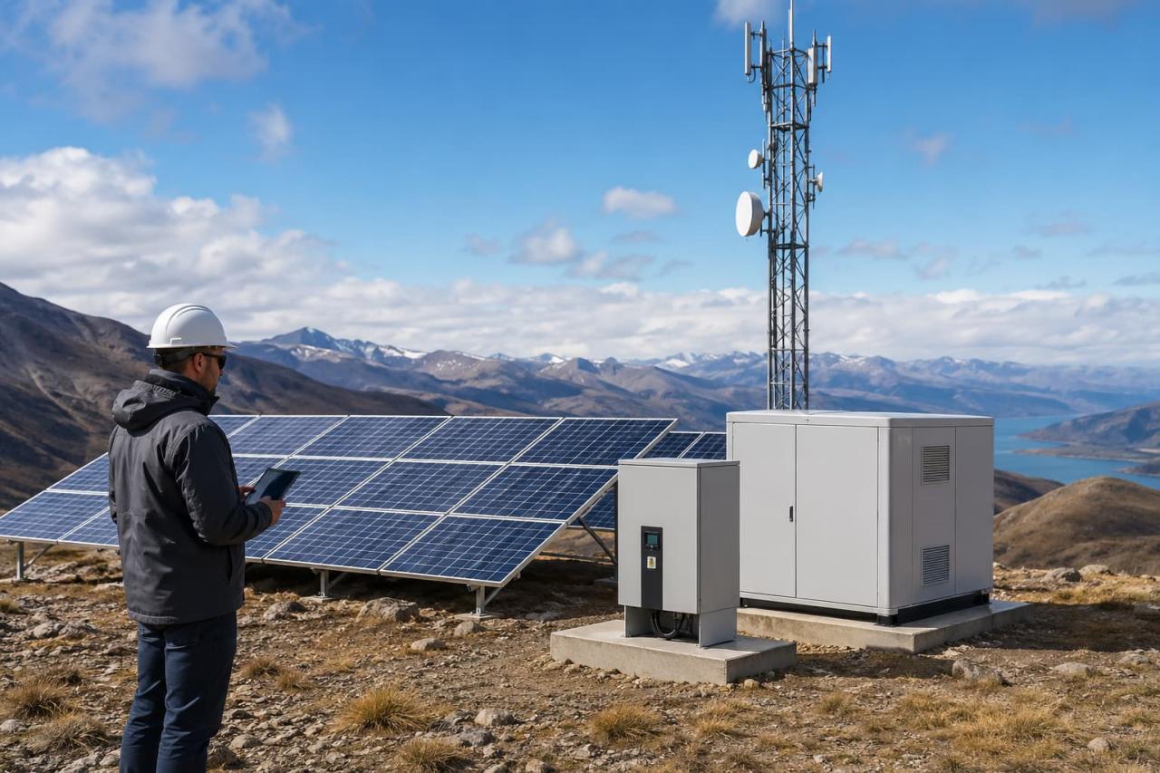
An off grid solar power system has no utility grid as a backup. When the battery runs low and the panels aren’t producing, there’s nothing else. That reality changes the engineering calculus entirely compared to a grid-tied system with battery backup. For commercial and remote-area projects, the stakes are higher. A telecom tower losing power means a service outage. A construction site losing power means lost shifts. Sizing must account for worst-case conditions — not average ones. That means modeling for low-solar-irradiance months, high-load peaks, and multi-day autonomy requirements simultaneously.
The sizing sequence always follows four steps: load calculation, battery sizing, array sizing, and inverter matching. Skipping or shortcutting any one of them compounds into a larger error downstream.
Solar Load Calculation for Off Grid Projects
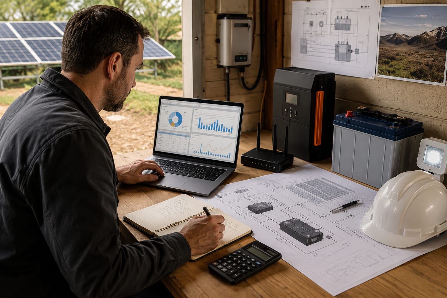
Load calculation is the starting point for every off grid solar power system design decision that follows. Before touching battery specs or panel counts, you need one number: how much energy the system must deliver every single day. That figure drives everything else. Rush this step, and every downstream calculation inherits the error.
Daily Energy Consumption Assessment
Load calculation starts with a complete inventory of every device the system must power. For each piece of equipment, you need two numbers: rated wattage and daily runtime in hours. Multiply them together to get watt-hours per device, then sum across all loads.
A practical example: a remote monitoring station running a 50W router for 24 hours, a 200W server for 12 hours, and 150W of LED lighting for 8 hours produces a daily load of 4,600 Wh — or 4.6 kWh/day. That number becomes the foundation for every calculation that follows.
Add a 20% buffer to your baseline figure. In real-world installs, clients consistently underreport consumption — equipment runs longer than expected, additional devices get added post-commissioning, and parasitic loads from idle electronics accumulate faster than anyone anticipates.
Peak Load vs Average Load
Daily kWh tells you how much energy the system needs. Peak load tells you how quickly it needs to deliver. These are different problems that require different solutions. Peak load determines inverter sizing. If multiple high-draw devices — motors, HVAC units, pumps — start simultaneously, the inverter must handle that surge without tripping. Industry benchmark: design inverter capacity for 125% of your calculated peak load to absorb startup surges safely. A system with a 4 kW peak draw needs at minimum a 5 kW inverter.
Battery Sizing for an Off Grid Solar Power System
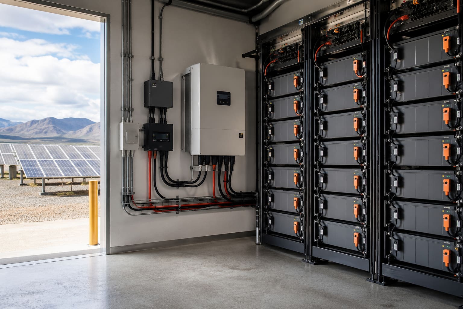
Solar battery storage sizing for an off grid solar power system comes down to three variables: daily energy consumption, required days of autonomy, and maximum allowable depth of discharge (DoD). Days of autonomy indicate how long the system can run without solar input. Most commercial projects target 2–3 days. Critical infrastructure sites often specify 5–7. Lithium iron phosphate (LFP) batteries dominate commercial off grid installations because they support 80% DoD without accelerating degradation. Lead-acid is limited to 50% DoD. That gap matters at scale — a 100 kWh LFP bank delivers 80 kWh of usable energy; the same nominal lead-acid bank delivers only 50 kWh.
The calculation: daily load (kWh) × days of autonomy ÷ DoD factor. For a 10 kWh/day load with 3-day autonomy and LFP at 80% DoD: (10 × 3) ÷ 0.8 = 37.5 kWh of nominal capacity required. Always round up — never down. One detail that gets overlooked: LFP cells must not be charged below 0°C without an integrated heating system. For remote-area projects, that’s a specification requirement, not an optional add-on.
Solar Panel Array and Inverter Sizing
Array sizing works backward from the daily load. The core formula: divide your daily energy requirement (in Wh) by the peak sun hours (PSH) for your installation location, then apply a system efficiency factor of 0.75 to account for real-world losses — wiring resistance, inverter conversion losses, and temperature derating on the panels themselves. For a 10,000 Wh/day load at a location receiving 5.5 PSH: 10,000 ÷ 5.5 ÷ 0.75 = approximately 2,424W of panel capacity required. In practice, that project would spec a 2.5–3 kW array to preserve headroom. PSH data for your specific site should come from verified sources such as the Global Solar Atlas — not regional averages.
Array sizing must use the lowest monthly PSH figure for the installation location, not the annual average. Systems sized to average irradiance perform well in summer and fail in winter. That’s a design error, not a weather problem. Inverter selection follows peak load calculation from Step 1. Beyond raw capacity, commercial projects require MPPT charge controllers matched to the array’s voltage and current output. A mismatch between the controller input voltage range and the array Voc under cold conditions is one of the most common commissioning failures on remote projects.

From Off Grid Solar Power System Design to Field Installation
Sizing outputs translates directly into installation specifications. Battery bank voltage determines busbar and cable configuration. String layout follows from array Voc and Vmp calculations. Run lengths set the minimum cable gauge. None of this gets decided on site — it comes from the numbers. Installation follows a fixed sequence: array first (disconnected from controller), then battery bank, then charge controller, then inverter last. Commissioning runs before any load connects — verify the battery state of charge, confirm the controller parameters match the battery chemistry, and check the inverter output under no load.
Introduce loads incrementally, lowest draw first. When commissioning throws surprises, the cause almost always traces back to a sizing assumption that didn’t hold in the field. Get the numbers right. The installation follows.