
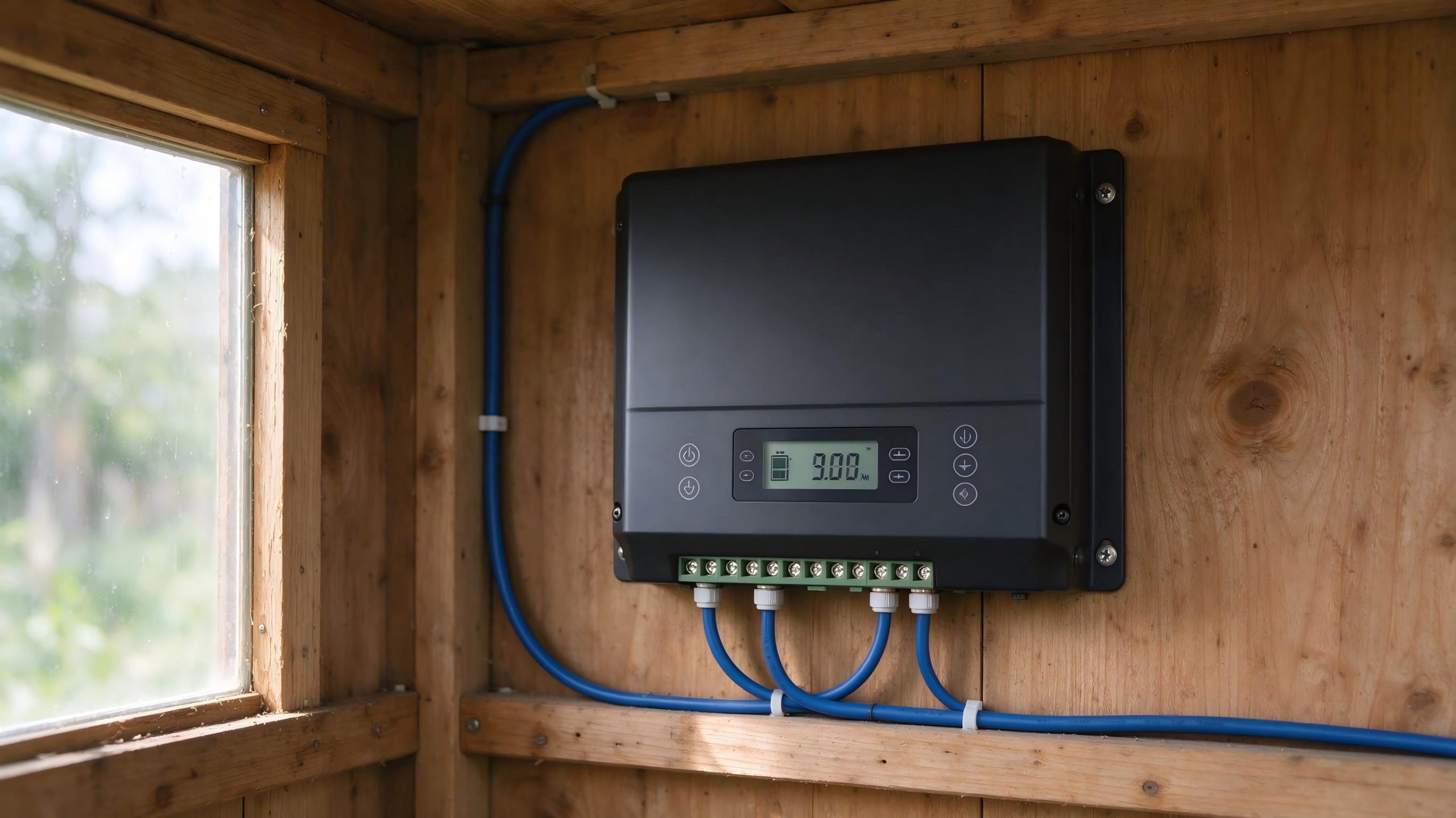
A PWM solar charge controller sits between a solar panel and a battery. It switches the connection on and off at high speed to hold the battery at its correct charging voltage. On a typical 12V shed or RV rig it is the cheapest controller you can buy. The catch is that it pulls the panel voltage down to the battery voltage, so any panel rated well above 12V gives up some of its watts. Size the controller for the panel’s short-circuit current, not the wattage on the box. Match the array voltage to the battery system. Set the battery profile to match the cell chemistry. Do those three things and the PWM controller runs the lights and the router without complaint.
What Is a PWM Solar Charge Controller?
A pulse width modulation solar charge controller is an electronic switch between the panel and the battery. When the battery is empty, the switch stays on most of the time. As the battery approaches its target voltage, the controller adjusts the switch’s duty cycle to reduce the average charging current. The panel does not see a fixed load. It sees a battery voltage, and it produces whatever current matches that voltage on its I-V curve.
How a PWM Solar Charge Controller Regulates Battery Voltage
A PWM controller regulates charging by rapidly switching the connection between the solar panel and the battery. As the battery approaches its target charging voltage, the controller adjusts the switch’s duty cycle to reduce the average charging current. For a typical 12V lead-acid battery, the charging profile may include bulk, absorption, and float stages. During bulk charging, the controller supplies available current until the battery reaches the absorption voltage. During absorption, it regulates voltage as the charging current tapers, then transitions to float when appropriate. The exact voltage settings and timing depend on the battery manufacturer’s specifications and the controller’s charging algorithm. Many modern PWM controllers offer multi-stage charging, but the supported profiles and settings vary by model. Always check the controller manual and the battery datasheet.
What Happens to the Panel Voltage
Here is the key point. When the PWM switch is on, the panel is hard-wired to the battery. The panel’s operating voltage gets pulled down to roughly the battery voltage. That means the panel does not run at its own maximum power point. It runs at whatever voltage the battery happens to be at. On a 12V system, that is often around 13 to 14V while charging. A panel rated at 18V Vmp will therefore deliver less than its rated wattage, because Vmp is where it makes the most power. This is not a defect. It is the trade-off that makes a PWM controller cheap.
PWM vs MPPT Solar Charge Controller
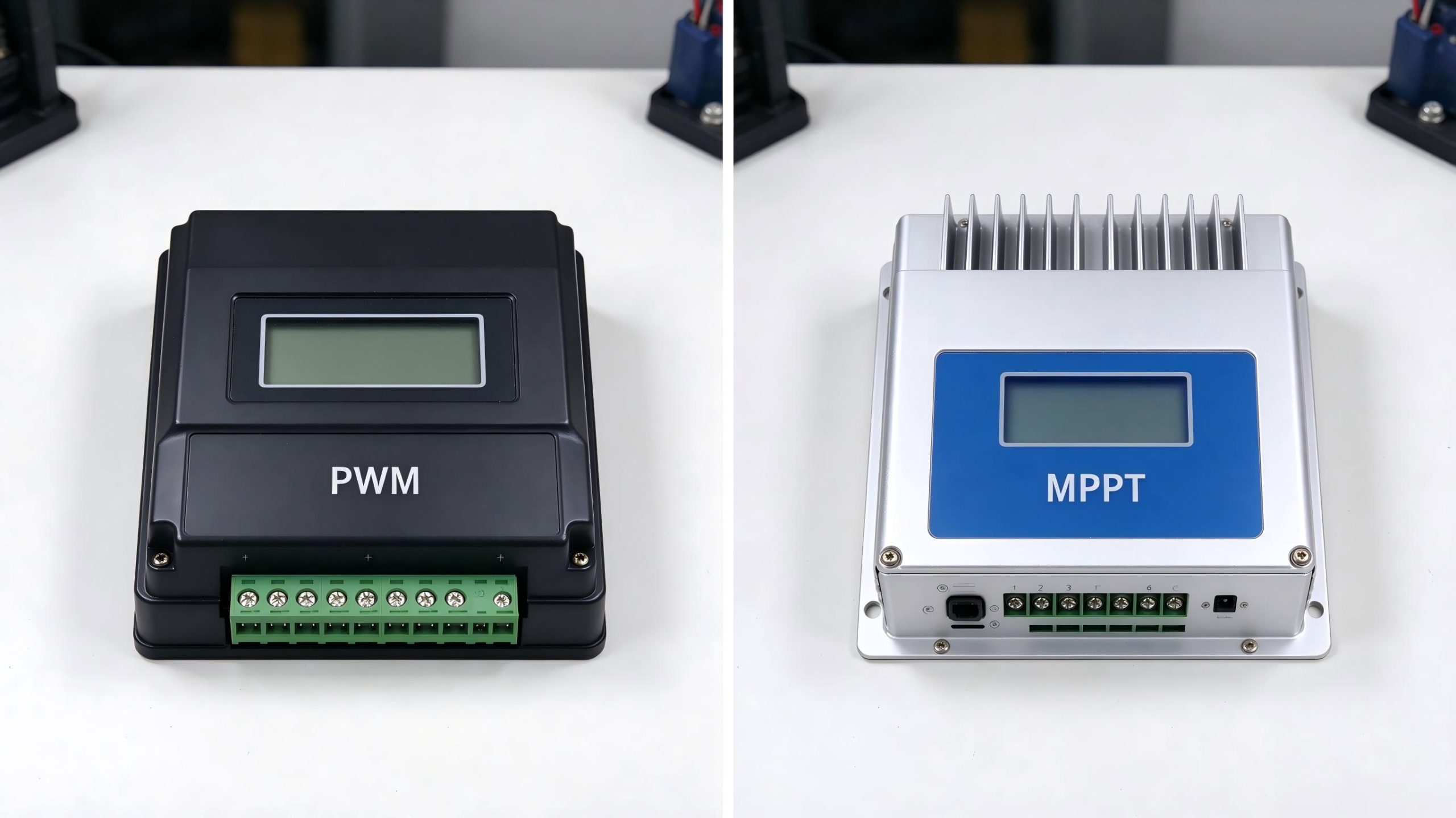
A PWM solar charge regulator and an MPPT controller both charge the same battery. They differ in how they treat the panel. The comparison below uses one panel and two controller types under the same sunlight, so the difference is clear.
Consider a 200W nominal 12V solar panel with a rated maximum-power voltage (Vmp) of 18V and a maximum-power current (Imp) of 11.1A. Its rated maximum power is approximately 18V times 11.1A, or 200W, under the specified test conditions. With a PWM controller charging a battery at 13.8V, the panel operates at a voltage closer to the battery voltage rather than its 18V maximum-power point. To estimate panel power at 13.8V, use the panel’s current-voltage curve to find the current at that voltage, then multiply 13.8V by that current. The current at 13.8V cannot be determined exactly from Vmp and Imp alone. An MPPT controller, by contrast, tracks the panel’s maximum-power point and converts the available power to the battery’s charging voltage, minus conversion losses. This is an illustrative comparison, not a guaranteed field result. Actual power depends on sunlight, cell temperature, wiring, and the controller’s specifications.
Where MPPT Gains the Most
MPPT pulls the biggest gain when the panel Vmp is well above the battery charging voltage. On cold days, the panel Vmp rises further, and MPPT captures more. On hot days, Vmp drops and the gap narrows. The exact gain depends on the panel temperature coefficient, the irradiance, and the battery voltage at the moment. It is not a fixed 10 to 20 percent number that applies to every system. A PWM controller on a panel rated close to the battery charging voltage loses very little. An MPPT controller on the same setup costs more and delivers almost nothing extra.
|
Factor
|
PWM controller
|
MPPT controller
|
|---|---|---|
|
How it handles panel voltage
|
Pulls panel operating voltage close to battery voltage while charging
|
Tracks the panel’s maximum power point and converts its output to battery charging voltage
|
|
Energy captured
|
Can lose available panel power when Vmp sits well above battery voltage
|
Generally captures more available panel power when there is a substantial voltage mismatch
|
|
Best fit
|
Small, low-cost systems with a suitably matched panel
|
Higher panel voltage, larger arrays, or a stronger need to maximize energy harvest
|
|
Efficiency information
|
Check controller losses and expected system performance in the manual
|
Check the specific model’s conversion-efficiency specifications
|
How to Size a PWM Solar Charge Controller
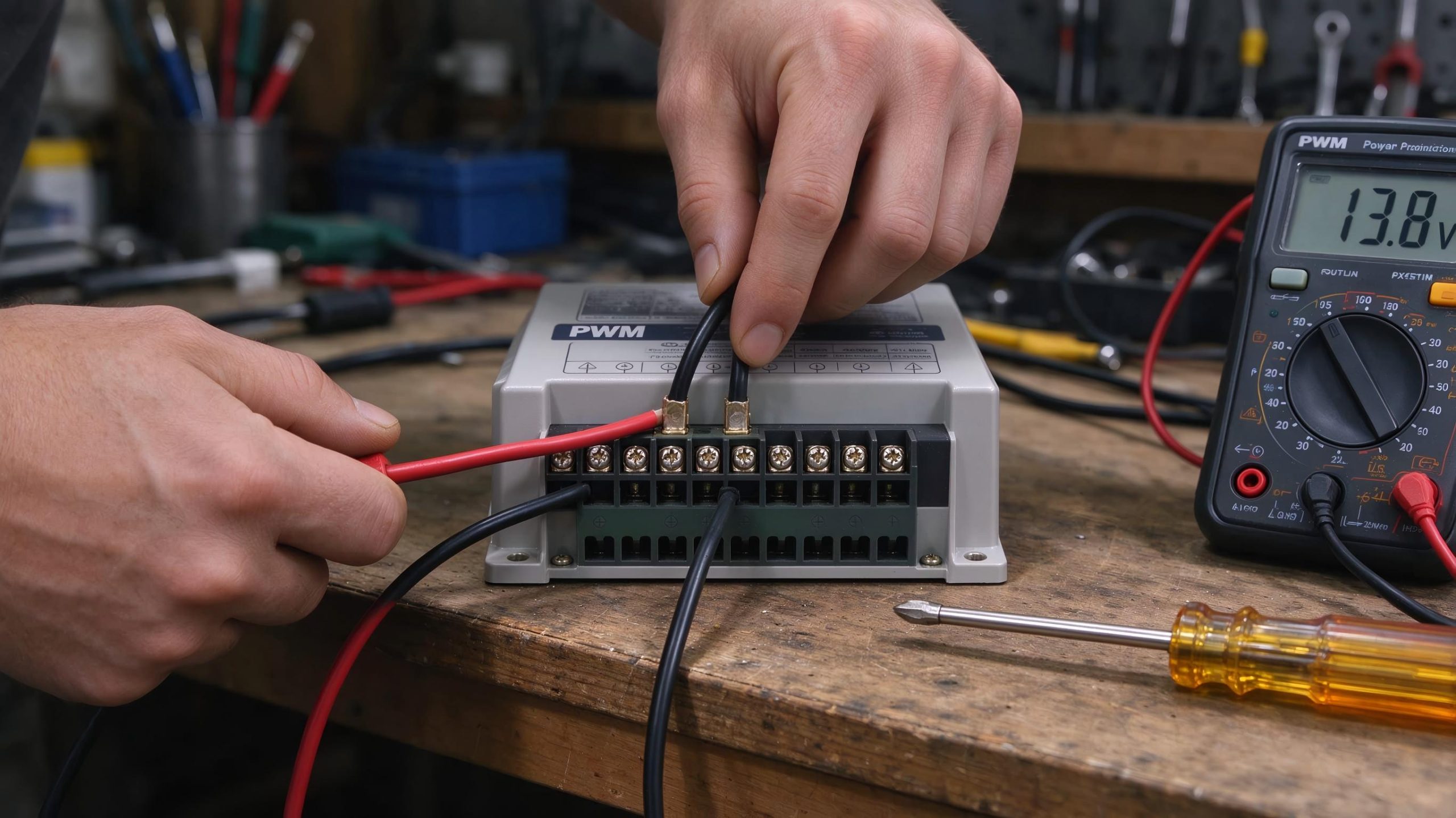
Sizing starts with the panel datasheet, not the box wattage. A PWM solar panel regulator is rated by the maximum current it can carry. If the panel pushes more current than the controller rating, the controller overheats. If you oversize wildly, you pay for amps you never use. Check four limits on the controller manual: rated charging current, permitted PV short-circuit current, maximum PV input power, and maximum PV open-circuit voltage at low temperature.
Start with Short-Circuit Current
Find the panel datasheet. Write down Isc, the short-circuit current. A typical 100W 12V panel lists Isc around 5.7A. Add a margin. A common rule is to size the controller for at least 1.25 times Isc, then check the manufacturer’s specific guidance. For one 100W panel at 5.7A, that gives 7.1A minimum. A 10A controller covers that. If you add a second 100W panel in parallel, Isc doubles to about 11.4A. Multiply by 1.25, and you get 14.3A. A 15A controller meets that minimum calculation. For three identical 100W panels in parallel, the combined Isc is about 17.1A. Applying the same 1.25 factor gives roughly 21.4A. A 25A or 30A controller may be suitable, depending on the manufacturer’s specifications and the system design. The 1.25 factor is a preliminary sizing calculation, not a substitute for the controller manual or applicable electrical requirements.
Check Voltage Compatibility
A PWM controller works best when the panel’s operating voltage is suitably matched to the battery’s charging voltage. A properly matched 12V nominal panel can often be used with a 12V battery system. For a 24V battery system, two compatible 12V nominal panels may be connected in series, but only if the controller is designed for the resulting array voltage. Add the panel Voc values together and account for the voltage increase at the lowest expected cell temperature. Confirm that the resulting cold-weather Voc remains below the controller’s maximum PV input voltage. Do not assume that every PWM controller can accept two panels in series. Check the controller’s voltage and power limits, as well as the manufacturer’s wiring instructions, before configuring the array. Also confirm polarity, cable gauge, overcurrent protection, and system ratings before wiring.
Check the Battery Chemistry Settings
Lead-acid, AGM, gel, and lithium batteries can require different charging profiles. Check the battery manufacturer’s recommended absorption voltage, absorption time, float voltage, and temperature limits before selecting a controller. A 14.4V charging setting is not automatically harmful to every lithium battery, but it may be unsuitable for a battery whose specifications require a different profile. Confirm that the controller supports the battery’s charging requirements, and disable lead-acid temperature compensation or equalization when required by the battery manufacturer. For lithium batteries, also check whether charging must be restricted at low temperatures and whether the battery management system provides the required protection. Follow the exact battery and controller manuals rather than relying on a universal voltage setting.
When a PWM Controller Is the Right Pick
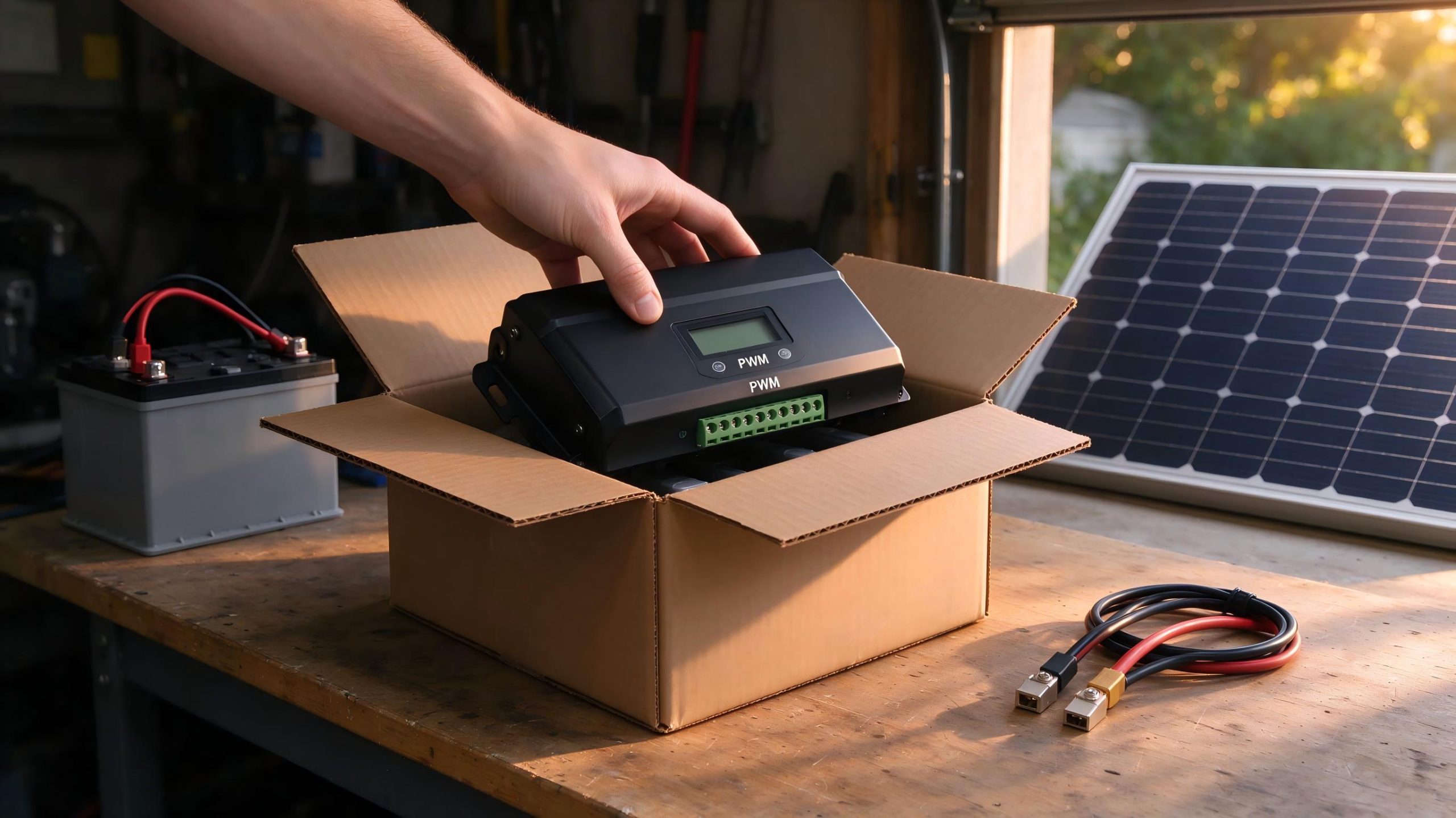
A small independent solar system on a shed, a cabin, or a camping rig is where PWM earns its place. It is cheap, it has no moving parts, and it is a well-understood topology when sized correctly. It loses ground on a large array, a cold climate, or a roof where the panel Vmp is far above the battery voltage. Match the controller current to Isc, leave margin, wire the array to match the battery nominal voltage, and set the battery profile correctly. The panel on the roof is already facing the sun. The controller just needs to carry the current without dropping the voltage.