
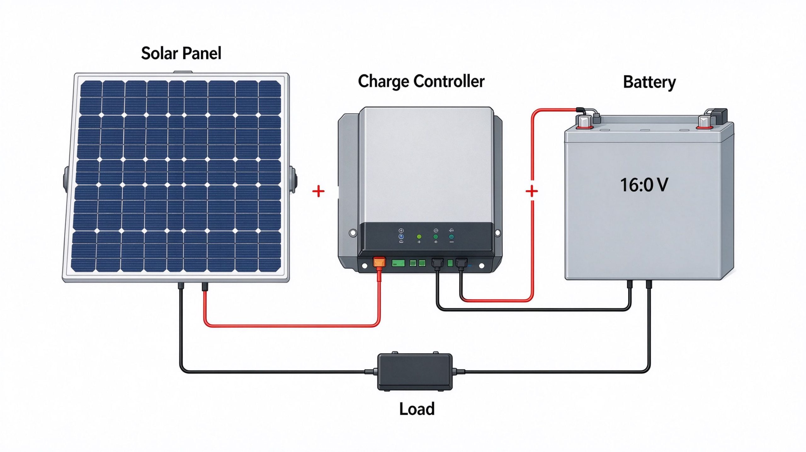
Solar panel cable size is chosen by current, run length, and allowable voltage drop, not by the panel wattage on the box. A wire that is too small overheats and wastes energy as heat. Oversized wire costs more to install than it saves. The right gauge for a 100W panel 2 meters from the controller is not the right gauge for the same panel running 15 meters to a shed. This guide walks through the parameters you need, the voltage drop calculation, and the checks you run before you buy the cable.
What Determines Solar Panel Cable Size?
Before you pick a gauge, collect the numbers that drive the calculation. The same 400W panel can require different cable sizes depending on system voltage, parallel string count, and cable run length.
Which Solar Panel Cable Size Do You Need?
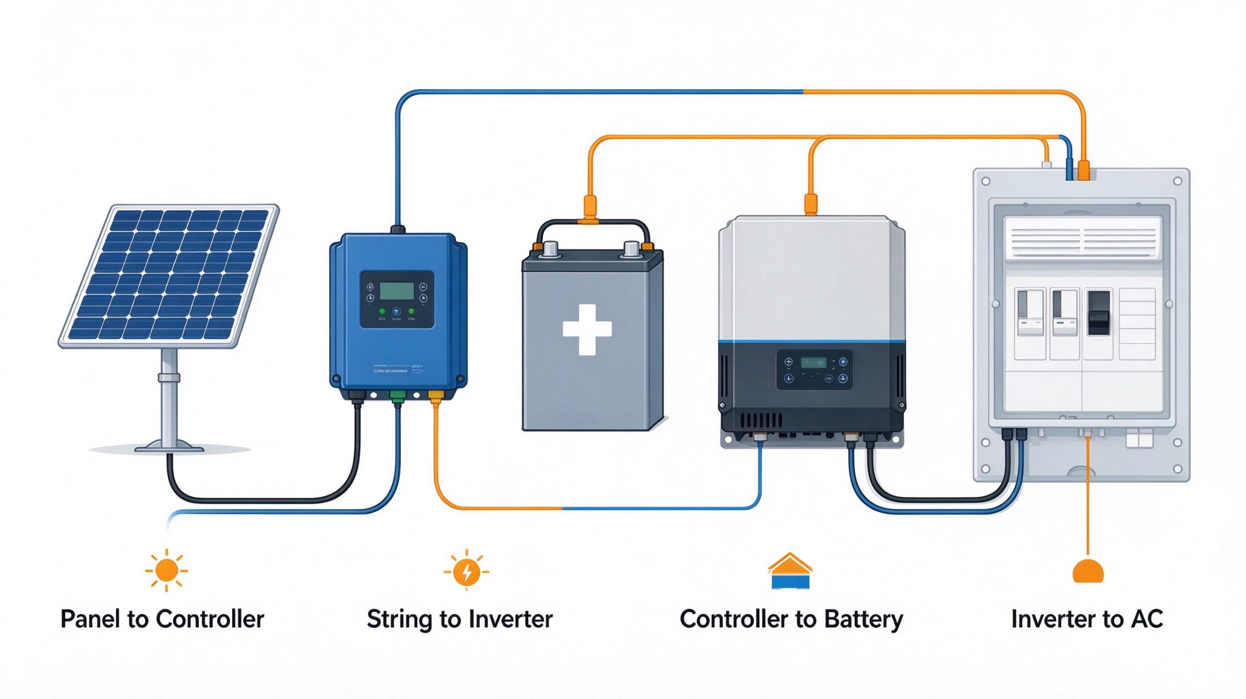
Do not size one cable and reuse it everywhere. A small off-grid rig has four distinct cable runs. Each one carries a different current and sits at a different voltage. The panel-to-charge controller cable carries the DC output at panel voltage. The string-to-inverter cable carries the combined DC from one or more strings. The charge controller-to-battery cable carries the charging current at battery voltage, which is the highest current in a 12V setup. The inverter-to-AC distribution carries the AC output and is sized by the inverter’s AC output.
How to Calculate Solar Panel Cable Size
The solar panel wire gauge calculation runs in five steps. Collect the current, measure the run, estimate the voltage drop, check ampacity under real install conditions, and then pick the standard size that meets all four limits.
Solar Panel Cable Size Step 1: Find the Solar Panel Current Rating
Start with the module datasheet and record the short-circuit current (Isc) and the maximum-power current (Imp). Imp is useful for estimating normal operating current and voltage drop. Conductor ampacity and overcurrent protection must be calculated according to the applicable electrical code and equipment instructions. For parallel-connected strings, add the relevant string currents when determining the array current. For series-connected modules, the string current generally matches one module’s current, while the voltages add. Do not choose the cable solely by dividing the panel wattage by 12. Before selecting the final size, check the required conductor ampacity, applicable correction and adjustment factors, overcurrent protection, and maximum system voltage.
Step 2: Measure the Cable Run Length
Measure the actual routed path, not the straight-line distance between two devices. Add the vertical drop from the roof, the conduit bend, and the run along the wall to the controller. For DC voltage drop, remember that current travels out on the positive conductor and back on the negative. The round-trip length is twice the one-way run L.
Step 3: Calculate Voltage Drop
Use the copper DC voltage drop formula as a starting estimate. Vdrop equals 2 × L × I × rho/A. L is the one-way length in meters. I is the circuit current in amps. rho is the resistivity of copper at the operating temperature, around 0.0175 ohm-mm^2/m at room temperature. A is the conductor cross-sectional area in mm^2. Convert Vdrop to a percentage of system voltage. A common design target is a maximum 3% drop on the PV source circuit and 1% on the battery circuit, but follow the applicable code and the equipment manufacturer. This is a first estimate. Terminals, connectors, and temperature all add extra resistance.
Worked example. A 100 W 12 V panel has Imp around 5.7A and a Vmp around 18V. The one-way run from panel to controller is 8 meters. The round trip is 16 meters. With 2.5 mm² copper, Vdrop is (16 × 5.7 × 0.0175)/2.5, or about 0.64V. For the panel-to-controller circuit, calculate the voltage drop percentage using the relevant operating voltage. Against a Vmp of 18V, that 0.64V drop is about 3.6 percent. Bump up to 4 mm squared, and the drop falls to about 0.40V, or 2.2 percent of Vmp. Bump again to 6 mm squared, and it lands near 0.27V, or 1.5 percent. The right size depends on your target drop and the applicable code.
Step 4: Check Current-Carrying Capacity
Voltage drop is only half the check. The cable must also carry the design current safely in the actual installation. Look up the ampacity for the chosen conductor size in the installed configuration. A cable in open air carries more than the same cable inside a conduit or bundled with other cables. A roof in full sun runs hotter than a cool basement. Derate ampacity for the installation method and ambient temperature. IEC 62548-1 covers design requirements for PV arrays, including cabling, protection, and isolation. Match the conductor, the overcurrent device, and the short-circuit rating as a set.
Step 5: Select the Final Cable Size
Compare two or three standard cross-sections. Choose the smallest size that meets the voltage-drop target, derated ampacity, and fits the overcurrent protection. Do not size by the panel wattage alone. Two panels with the same wattage can have different Isc values depending on cell technology, voltage class, and efficiency.
Solar Cable Size Chart and How to Choose the Right Cable
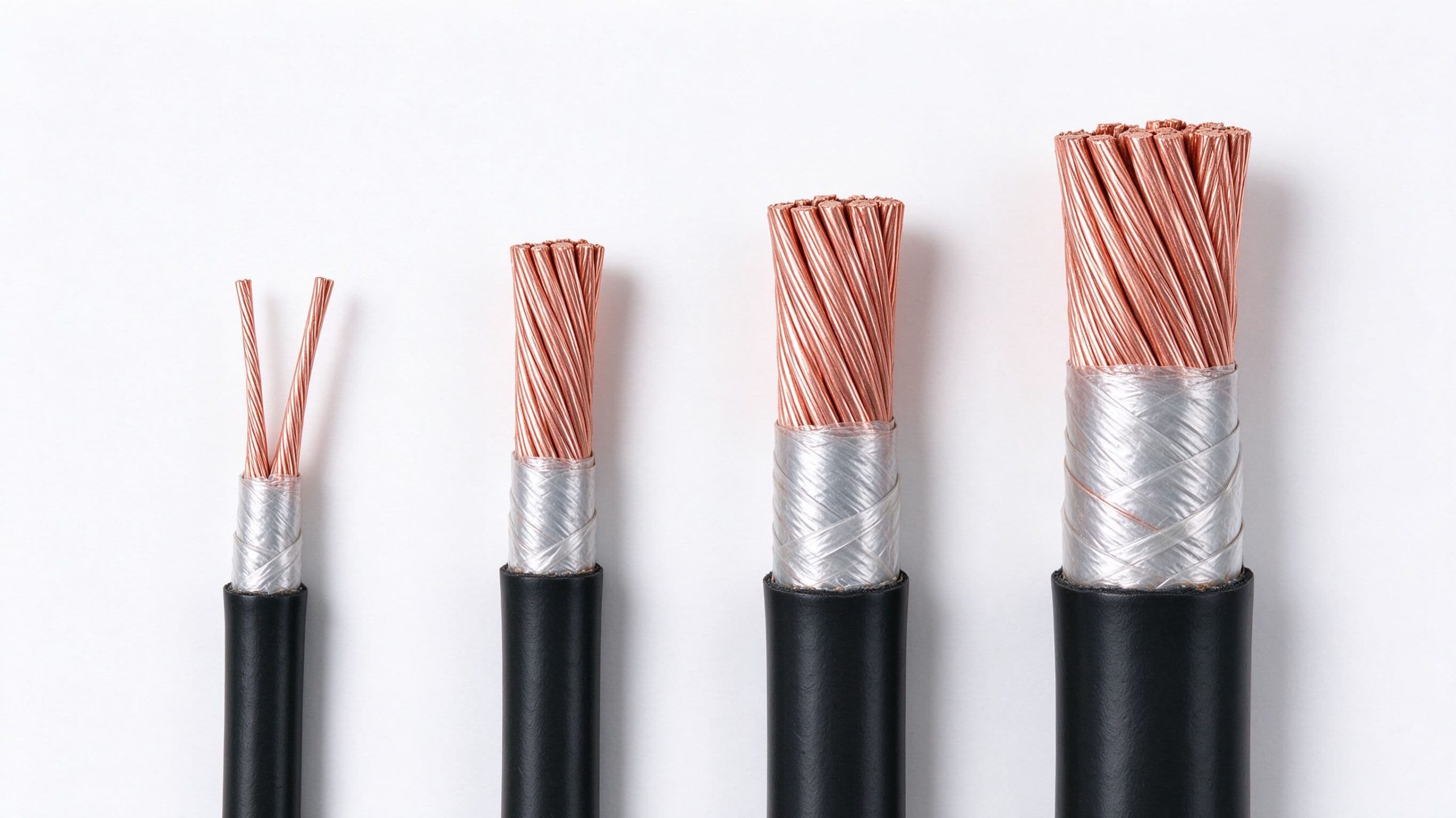
The PV cable size you buy includes a cross-sectional area (mm² or AWG), a voltage rating, and a jacket type.
Residential and small off-grid rigs run a small set of standard sizes. The table below pairs common metric cross-sections with approximately comparable AWG conductors. Do not treat the two as directly interchangeable. AWG copper cross-sections don’t match the metric values, and you still need to check ampacity, insulation rating, and terminal compatibility separately.
|
Metric conductor
|
Approx. AWG reference
|
Note
|
|---|---|---|
|
1.5 mm2
|
14 AWG
|
AWG conductor is larger
|
|
2.5 mm2
|
12 AWG
|
Do not substitute the smaller 14 AWG
|
|
4 mm2
|
10 AWG
|
Verify ampacity and terminals
|
|
6 mm2
|
8 AWG
|
Ampacity is not automatically equal
|
|
10 mm2
|
6 AWG
|
Calculate for each circuit
|
|
16 mm2
|
4 AWG
|
Check protection and terminals
|
|
25 mm2
|
3 AWG
|
Verify cable and equipment specs
|
Use this table as a starting reference only. The actual size depends on your current, run length, temperature, and allowable drop. Each DC source circuit, battery circuit, and AC inverter output needs its own calculation. Do not reuse one gauge across the whole system.
How to Choose the Right Solar Cable Type
Choose a cable approved for the intended PV circuit, voltage, temperature, moisture exposure, and installation method. For exposed PV wiring, use appropriately listed photovoltaic wire, such as cable compliant with the applicable UL 4703 or IEC 62930 requirements. Conductors installed inside conduit must also comply with the applicable wiring method and local electrical code. Do not assume that a cable is suitable for rooftop PV use simply because it is rated for building wiring. Check the actual cable markings and the manufacturer’s installation instructions. Avoid using ordinary non-PV cable for exposed rooftop runs unless the specific wiring method and cable rating are permitted by the applicable code.
Copper vs. Aluminum Solar Cables
Copper is the default for small PV systems. It has lower resistance, smaller connectors, and reliable terminations. Aluminum conductors generally require a larger cross-section than copper conductors for comparable electrical performance. Use terminals and connectors rated specifically for aluminum conductors, prepare the connection as the manufacturer instructs, and apply antioxidant compound when the connector specifications require it. Tighten all terminals to the specified torque. Do not swap a copper gauge for an aluminum gauge with the same printed cross-section. Ampacity and voltage drop numbers differ. For small off-grid rigs and battery connections, copper is almost always the right call.
How to Install and Check Solar Panel Cables Safely
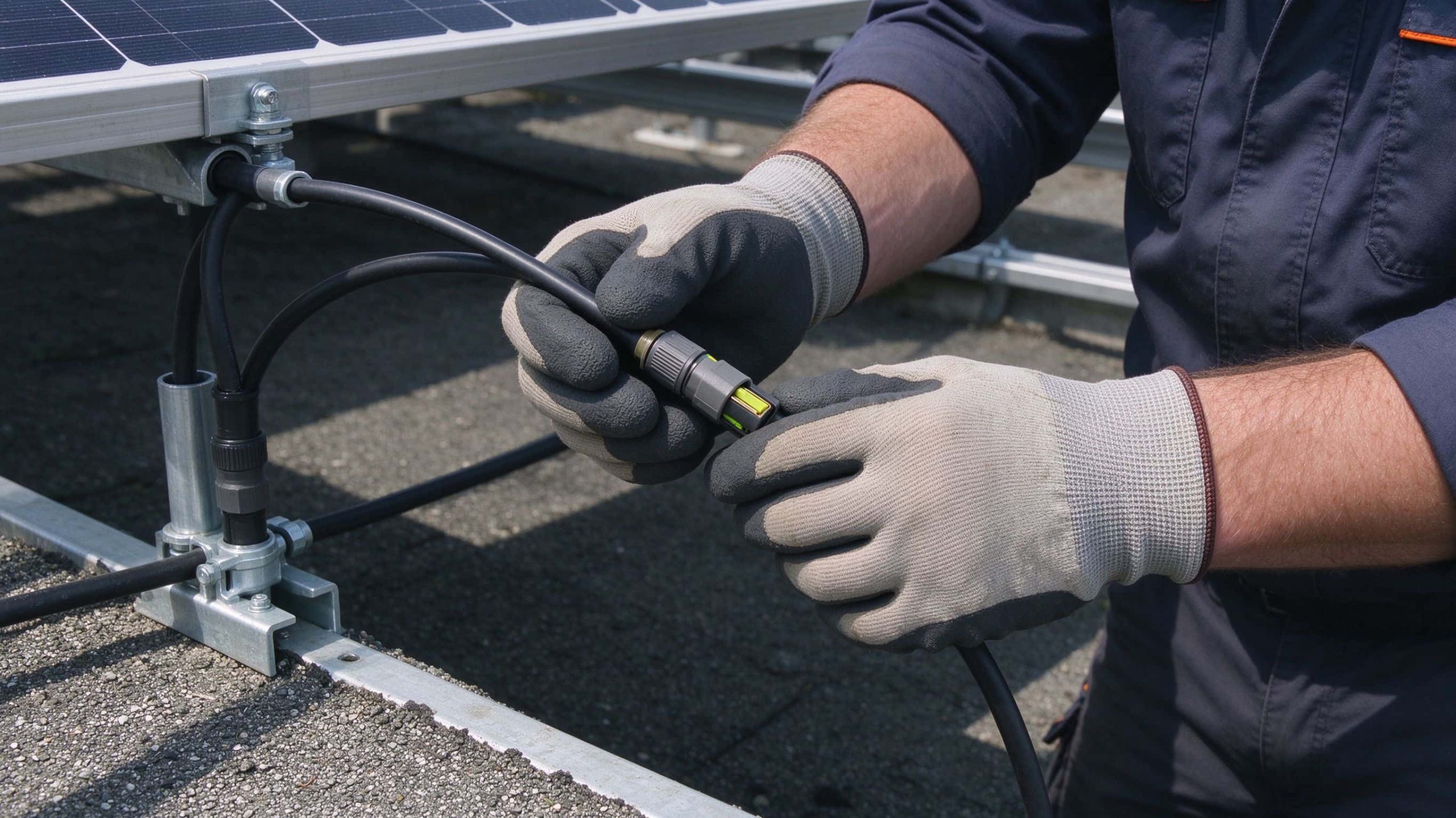
The solar panel wire size on paper only helps if the install matches the calculation. Verify the cable voltage rating is above the system Voc. Check that the temperature rating matches the roof environment. Use connectors rated for the cable, the current, and the voltage. Do not mix connector brands just because they click together. MC4-style connectors from different manufacturers aren’t always fully compatible. Crimp the contacts with the correct tool. A hand-twisted joint on a DC roof circuit fails.
Inspect Cable Routing and Connections
Solar panel cable size should not rub on sharp panel edges or sit in puddles. Keep bends above the minimum bend radius printed on the jacket. Route DC and AC cables separately where the code requires it. Confirm polarity at every connection. Reversed polarity can damage the charge controller and other connected equipment. Verify polarity at every connection and follow the manufacturer wiring sequence before energizing the system—torque every terminal to the manufacturer’s value, not to a finger-tight plus a guess.
Common Solar Cable Sizing Mistakes
The most common sizing errors are easy to spot once you know what to look for. Sizing by panel wattage instead of current. Calculating voltage drop but ignoring ampacity derating in a hot conduit. Forgetting that bundled cables share heat and need a smaller current. Copying the panel-to-inverter cable size onto the battery circuit, where the current is much higher on a 12V system. Using ordinary outdoor wire on the roof instead of a UV-rated PV cable. Treating a live DC connector like an AC plug and pulling it apart under load.
Safety note. PV panels produce DC voltage whenever they are in daylight, even before the battery is connected. Do not disconnect live DC connectors under load. Do not open roof combiner boxes or work on strings above the voltage level your equipment and training cover. Roof arrays, high voltage strings, and main DC disconnects should be handled by a qualified electrician.
Solar Panel Cable Sizing: Final Checks Before You Wire
The right solar panel cable size must meet four requirements: adequate current-carrying capacity, acceptable voltage drop, compatible overcurrent protection, and suitability for the installation environment. Calculate each circuit separately using its design current, actual cable route, operating voltage, and applicable electrical code. Then verify the cable voltage, temperature, and environmental ratings. For rooftop arrays, high-voltage DC circuits, and main battery connections, have a qualified electrician confirm the final design. Choosing a cable is not just about avoiding wasted power. It is about keeping the whole circuit safe and reliable for the life of the system.