

A buyer choosing a microinverter for solar panels may see two or four DC connectors and assume that the same number of modules can be connected safely. That assumption can create an expensive mismatch. Connector count sets a physical limit, but voltage, current, MPPT design, module power, temperature, and AC branch capacity also affect the final answer. Most microinverters serve one, two, or four modules. The approved number for a specific unit must come from its datasheet and installation manual. Before pairing any panel with a Micro Inverter, check every input against the module’s electrical data and the lowest expected site temperature.
The Short Answer Is Usually One, Two, or Four Modules
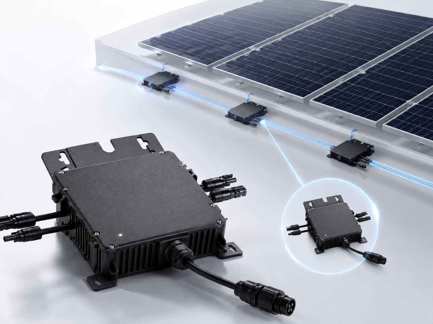
A microinverter normally accepts one module on each approved DC input. A single-input model serves one module, a dual-input model may serve two, and a four-input model may serve four. Some multi-input units provide an independent MPPT channel for every input. Others share an MPPT channel across a pair of inputs, so panel orientation and shading conditions need closer review.
| Microinverter design | Common module arrangement | Main question to confirm |
|---|---|---|
| Single-input | One module | Does the module fit the voltage, current, and power limits? |
| Dual-input | Up to two modules | Does each input have independent MPPT control? |
| Four-input | Up to four modules | Are any inputs or MPPT channels shared? |
An unused input does not make the unit unsafe when the manufacturer permits partial loading and supplies the required sealing cap. Connecting two panels to one input with an unapproved splitter is different. That change can raise current beyond the connector, cable, or input rating. Never create a series or parallel arrangement unless the manufacturer lists it as an approved configuration.
Input Count Does Not Prove Module Compatibility
The number of sockets provides only part of the answer. A valid match requires the solar module to stay within the microinverter’s electrical operating window under real site conditions. Microinverters perform DC-to-AC conversion close to the panel. Each input receives DC power from its connected module, tracks an operating point, and sends converted AC power to the branch circuit. If the panel voltage falls outside the MPPT range, the inverter may start late, stop early, or lose energy. Excess voltage or current can exceed an equipment rating and create a safety risk.
The correct module count is therefore the lowest approved limit produced by three checks:
- The number of usable DC inputs.
- The electrical match at every input.
- The number of microinverters allowed on the AC branch circuit.
Passing one check does not compensate for failing another.
Six Specifications Decide How Many Panels a Microinverter Can Handle
A compatibility review should compare the exact panel datasheet with the exact microinverter datasheet. Product family names are too broad because ratings can change between models, power classes, and regional versions.
1. DC Input Count
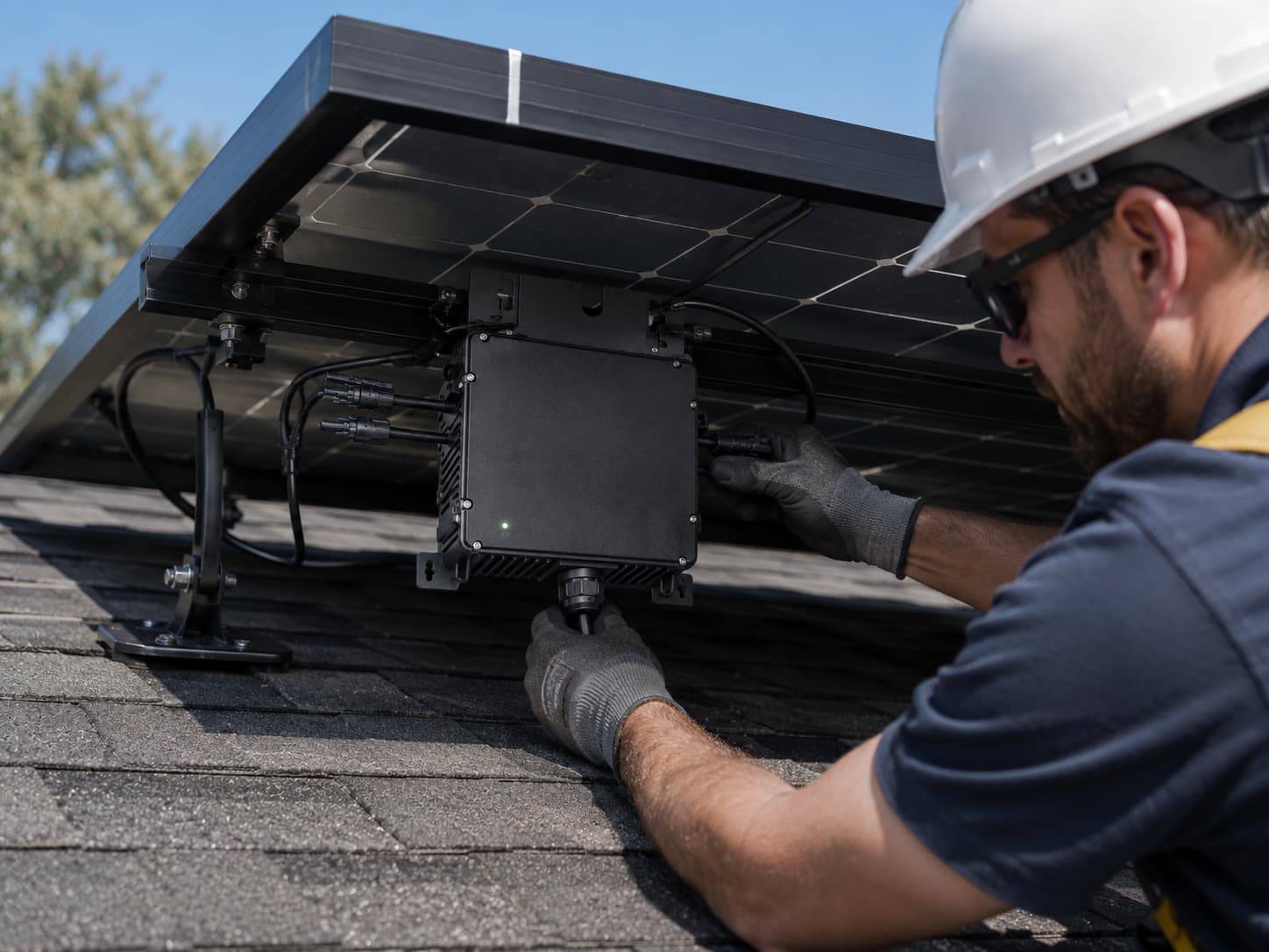
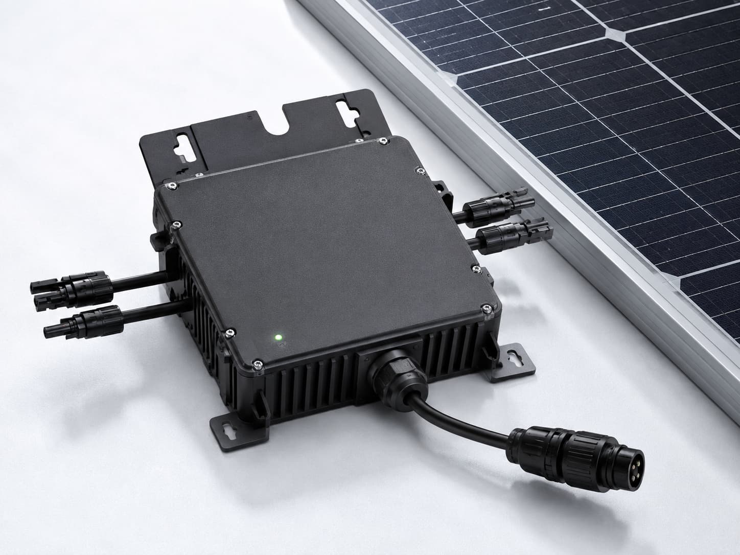
Count the approved module inputs, then check the installation manual for permitted loading patterns. A four-connector enclosure does not always mean four fully independent channels. The manual may assign two inputs to one MPPT tracker or require specific input positions when you install fewer modules.
2. Maximum DC Input Voltage
Find the panel’s open-circuit voltage (Voc) and the microinverter’s maximum input voltage. Solar module voltage rises as cell temperature falls. For this reason, comparing the STC Voc printed on the panel datasheet directly with the inverter limit is incomplete. Use the module’s temperature coefficient and the site’s lowest design temperature to calculate the cold-corrected Voc. The result must remain below the microinverter’s maximum input voltage, with any margin required by the manufacturer and local electrical rules.
3. MPPT Operating Range
The module’s maximum-power voltage, or Vmp, should fall within the inverter’s MPPT operating range under normal hot and cold conditions. A panel can stay below the maximum voltage limit and still perform poorly if its operating voltage spends too much time outside that range. Review the starting voltage as well. A high starting threshold may delay production during low-light mornings, although the final effect depends on the module, irradiance, temperature, and inverter design.
4. Input Current and Short-Circuit Current
Compare the panel’s operating current (Imp) with the maximum continuous input current. Compare its short-circuit current, Isc, with the microinverter’s stated short-circuit input limit. Apply the calculation method and safety margin required by the equipment instructions and the electrical code used at the project location. High-current modules deserve extra attention. A module can have suitable wattage and voltage while its current still exceeds the input rating. In that case, choosing a higher-current microinverter input is safer than assuming the inverter will simply clip the excess.
5. Recommended Module Power
Manufacturers often publish an accepted or recommended module power range. A panel with a higher STC rating than the microinverter’s AC output is not automatically incompatible. The inverter may clip output for part of a bright day, while the larger module may improve production during weaker light. The DC-to-AC ratio should still reflect the climate, panel orientation, shading, electricity value, and expected clipping. A supplier should model this relationship instead of selecting the largest panel that fits the connector.
6. AC Output and Branch-Circuit Limits
The number of modules per microinverter is a DC-side question. The number of microinverters on one AC branch is a separate system limit. Check the unit’s rated AC output current, cable system, overcurrent protection, branch voltage, conductor capacity, and the manufacturer’s maximum units-per-branch table. Local grid rules may also require an approved grid profile, rapid shutdown behavior, anti-islanding protection, or specific certification. These requirements affect the acceptable model and system layout even when the module inputs match.
A Compatibility Worksheet Prevents Costly Assumptions
The example below shows how a buyer can organize a review. The values are hypothetical and do not describe a Homesolars product. Replace every number with data from the two selected model datasheets.
| Compatibility check | Example module | Example microinverter input | Initial result |
| Module quantity | Four modules | Four DC inputs | Possible, subject to the other checks |
| Vmp at STC | 34.5 V | MPPT range: 28-48 V | Inside the published range at STC |
| Voc at STC | 41.2 V | Maximum input: 60 V | Cold-temperature calculation still required |
| Imp | 12.8 A | Maximum continuous input: 14 A | Within the stated limit |
| Isc | 13.7 A | Maximum short-circuit input: 15 A | Local calculation and required margin still need review |
| Module power | 440 W | Accepted range: 300-500 W | Inside the example range |
This initial worksheet does not authorize installation. It identifies missing checks. In the example, the cold-corrected Voc and applicable Isc calculation remain unresolved. The buyer must also confirm the MPPT arrangement, connector type, approved cable system, branch-circuit count, and grid requirements. A useful procurement file should include the module model number, microinverter model number, both datasheets, the lowest site temperature, the proposed branch layout, and the applicable electrical standard. Keeping those records also makes future replacement and expansion easier.
Independent MPPT Channels Affect the Layout Decision
Two microinverters can have the same input count and still behave differently on a roof. The difference often comes from MPPT channel design. Independent MPPT channels can help when panels face different directions or receive different shading. Each connected module can operate near its own maximum-power point. A shared MPPT arrangement may work well for modules with similar orientation and sunlight, but mismatched conditions require more careful design.
Do not treat independent MPPT as permission to mix arbitrary modules. Voltage, current, connector, and approved power limits still apply. If two panel models have different electrical characteristics, request written compatibility confirmation before combining them in one system.
Common Module-Matching Mistakes
Most failed selections come from skipping one data point or confusing a DC input limit with an AC system limit. These mistakes are common during quotations and later system expansion.
- Counting connectors without checking how the MPPT channels are arranged.
- Using panel wattage as the only compatibility test.
- Comparing voltage at STC without calculating cold-weather Voc.
- Treating current clipping as protection against an excessive input-current rating.
- Connecting multiple modules through an unapproved splitter.
- Ignoring connector make, cable rating, sealing caps, and installation instructions.
- Adding microinverters without recalculating the AC branch-circuit limit.
- Assuming a grid-tied microinverter will supply power during an outage. Standard grid-following equipment normally shuts down when the grid signal disappears unless the complete system is designed and approved for backup operation.
Buyers reviewing other solar equipment should use the same model-specific approach. Panels, cables, protection devices, monitoring hardware, and mounting conditions all influence the final microinverter layout.
Questions to Send the Supplier Before Ordering
A short technical request can prevent repeated quotations and incompatible deliveries. Send the exact solar panel model and expected quantity, then ask the supplier to answer these questions in writing:
- How many modules can connect to this exact microinverter model?
- How many independent MPPT channels does it have?
- What are the maximum DC voltage, MPPT range, starting voltage, continuous input current, and short-circuit input limits?
- Has the supplier checked cold-corrected Voc for the installation location?
- Is the module power inside the approved or recommended range?
- What DC connector and AC cable system does the installation require?
- How many units can share one AC branch at the selected grid voltage?
- Which grid certifications and protection functions apply in the destination country?
- Does the system support module-level monitoring?
- What design changes are needed for future expansion or battery backup?
For complete solar energy solutions, the supplier should return more than a unit price. Ask for the proposed electrical layout, compatibility records, cable and protection requirements, monitoring architecture, and commissioning checks. Commercial buyers can also compare the plan with similar solar projects before approving a bulk order.
A Microinverter Handles Only the Modules Its Limits Support
One module per DC input is the practical starting point, so a single-, dual-, or four-input microinverter usually serves one, two, or four panels. The final number is valid only after every module passes the voltage, MPPT, current, power, connector, temperature, and installation-manual checks. For purchasing, send the exact panel and microinverter model numbers to the supplier and request a written compatibility review. If the cold-weather voltage, input current, MPPT arrangement, or AC branch limit remains unclear, do not approve the configuration yet. Those values decide how many modules the microinverter can handle safely and how reliably the finished system will operate.